Functional Description
The Pertronic Isolate Timer Module (ITM) provides a Countdown Timer to isolate a zone for
a pre-determined period. For example, it may be used to isolate devices in a particular zone,
when work performed in that zone may otherwise cause an alarm to sound.
The Pertronic ITM:
- Allows a zone to be isolated at the push of a button.
- Provides the ability to isolate a zone for a user-defined period of time.
- Provides two separate clean-contact changeover connections for external equipment.
- Has both clean contact outputs active during the Isolate condition.
- Provides visual indication that the zone has been isolated by the panel.
- Provides Visual and Audible warnings that the isolated countdown period is about to expire.
- Connects to and is powered from the Pertronic analogue addressable loop.
- Can be used to isolate Vesda equipment connected to Pertronic Fire Alarm Panels, or connected to 3rd Party products.
- Is mountable in standard single-gang flush or surface-mount electrical fittings, and is supplied with a protective plastic cover for installation during building construction.
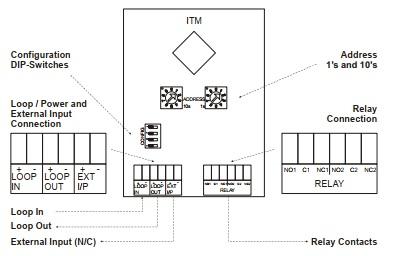
Block Diagram
Dip Switch
SW1-1 Selects operating mode:
OFF: ITM operates in analogue addressable mode
ON: ITM operates in standalone mode
SW1-2 Selects the mode in which the Ext Input operates during stand-alone mode only:
OFF: Ext Input is used to lock keypad. Normally closed to operate ITM, open to lock buttons
ON: Ext input used for Alarm feedback indication. An open circuit on input displays a ‘A’ on the LCD
SW1-3 Selects country mode:
OFF: New Zealand
ON: Australia
SW1-4 Used in the factory only:
OFF: Normal
ON: Factory Test
Defect Messages
| Defect Message | Description |
|---|---|
| dEF 1 | Address ‘n’ loop communication, has been lost for more than one minute* |
| dEF 2 | Address ‘n+1’ loop communication has been lost for more than one minute* |
| dEF 3 | Either Isolate or De-isolate button has been pressed and held for more than 15 seconds |
Panel Configuration
The F100A, F120A and F220 panels require specific configuration setups for the ITM to operate correctly:
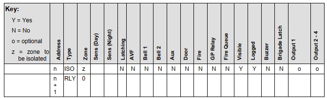
- The device at the ITM’s base address must have the type ISO and have its zone number set to the zone that requires isolating. No more than one zone can be isolated by the ITM.
- The device at the ITM’s second address (base address +1) must have the type RLY and have its Zone number set to 0.
These apply to both panels; the specific configuration steps for each panel are shown below.
F100A-256 Analogue Addressable Panel (s/w 5.xx)
The ‘Visible’ and ‘Logged’ flags for the ITM device address should be set to YES; all other flags remain un-configurable. In ‘Zones,’ map the respective Zone’s ‘Isolated Alarm’ output to the ITM RLY device. This will activate the Alarm Indication on the ITM LCD by displaying ‘A’ (for alarm) when the isolated zone is in alarm. In the Zone menu for the respective Zone, map from output ‘Isolated Alarm’ to the ITM’s relay address as shown below.
F120A Analogue Addressable Panel
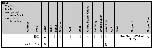
By default, all flags will remain un-configured, except for the RLY device’s “Zone Trip” flag,
which must be set to No. Map an output of the ITM’s ISO device to the ITM’s RLY device, set
to activate on a ‘Pre-Alarm’. This will activate when the zone ISO switch is active and there is
an alarm condition in the mapped zone.
Note that, although we are activating via a ‘Pre-Alarm’ event, the ‘Pre-Alarm’ event is simply
used to instruct the F120 to operate in Zone Isolate Mode. If the ‘Pre-Alarm’ qualifier is not
used, then the output will simply trigger when the ISO switch is active, regardless of the alarm
state of the zone.
F220 Analogue Addressable Panel
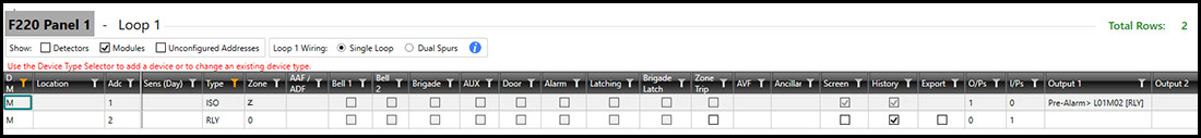
F220 configuration is the same as F120A