Videos
Reprogramming Input 2's default tone
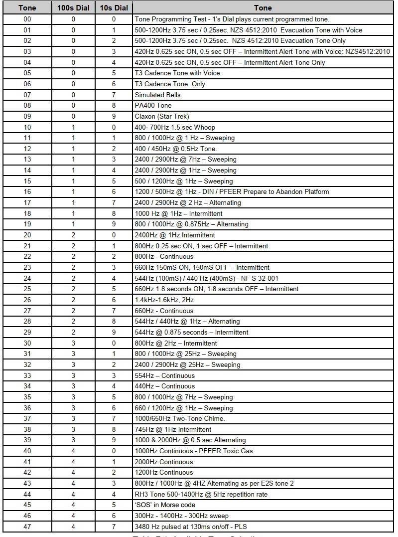
Changing input 2's default tone of 3 to tone 12
Configuration switches demonstration
Demonstrating the EVAC50W24V's four config switches
Class Change duration
How to change the EVAC50W24V's class change tone duration time
Config Jumper assignments
LK 1 – disable bell input requirement
With Config Link LK1 fitted, the amplifier activates without the need of a bell signal when activating inputs 1, 2 or 3. Applying a ‘Bell on’ condition with Config Link LK1 fitted and any input active or inactive results in the amplifier activating tone 1 With the LK1 omitted, a bell ‘on’ signal and activation of an input is required to turn on the amplifier. RS485 LED activations work as normal.
LK 2 – enable Class Change (School Bell mode)
With Config Link LK2 fitted, class change for input 3 is enabled (eliminating the previous programming requirement) and remains enabled when the ‘Silence Alarms’ (BCO) is active. Class Change can also be activated via RS485 LED mapped activation Amplifier LED base address +2. With LK2 omitted class change is not enabled. Tone burst length still needs to be programmed as described in the manual with the 1’s dial set to 5 (not 7 as for earlier firmware versions).
LK 3 – Disable Amplifier
With Config Link LK3 fitted, activating inputs 1 or 2 will activate the amplifier, provided input 3 is not active. With Config Link LK3 fitted, activating input 3 results in disabling the amplifier (which also prevents class change operation if LK2 were fitted). With Config Link LK3 fitted, activating Amplifier LED base address +2 also results in disabling the amplifier.
LK 4 – LCD address mode
With Config Link LK4 fitted, the Amplifier is polled as an LCD mimic instead of as an LED mimic and responds to LED mapped RS485 activation of Amplifier. This is to overcome the limitation of the maximum 8 polled LED mimic addresses and so allows up to 16 polled amplifiers, 8 as LED mimics and 8 as LCD mimics. Any defect from an amplifier set as LCD mimic is signalled as ‘LCD mimic address missing’ defect by the panel.
Defect Table
| Defect | Bell Circuit Monitor | RS485 Message | Defect LED |
|---|---|---|---|
| DC Power Supply Missing | EOL clamped to 4kΩ | LED Mimic xx Missing | OFF |
| DC Power Supply 'Off Normal' | EOL clamped to 4kΩ | LED Mimic xx Defect Int. | 1st Flash Long |
| Amplifier Output Low or Overload Defect, or MJ6 not fitted | EOL clamped to 4kΩ | LED Mimic xx Defect Int. | 2nd Flash Long |
| 100V 10kΩ EOL Defect | EOL clamped to 4kΩ | LED Mimic xx Defect | 3rd Flash Long |
| RS485 Communication Defect | EOL clamped to 4kΩ | LED Mimic xx Missing | 4th Flash Long |
| DC Power Supply 'Off Normal' History | Normal | Normal | 5th Flash Long |
| Amplifier Output Low or Overload Defect History or MJ6 not fitted | Normal | Normal | 6th Flash Long |
| 100V 10kΩ EOL Defect History | Normal | Normal | 7th Flash Long |
| RS485 Communication Defect History | Normal | Normal | 8th Flash Long |
| Amplifier Isolated | EOL clamped to 4kΩ | LED Mimic xx Defect | 9th Flash Long |
Bell Mode
The BELL circuit may operate in one of two modes configured by link MJ5 labelled 'BELL MODE'.
NORM: with the link placed in the normal position, a positive voltage on the BELL input activates the amplifier. When an ‘Off-Normal’ condition occurs the amplifier changes the BELL circuit EOL resistor value.
CCNC: with the link in the 'CCNC' position, the BELL input becomes a Clean Contact, Normally Closed relay output for external defect monitoring. Voltage must not be applied to the BELL input in CCNC mode because the normally-closed contact is a short circuit.
Tone Selection Table