Masterboard Config Link Settings
| Function | |
|---|---|
| Auxillary Relay Board or RMAX board fitted
|
MJ5 link removed |
| DBA on circuit 4. |
MJ4 link fitted |
| Defect Buzzer
|
MJ3 link fitted |
| NZS4512: 2003 mode. |
LK1 link fitted |
| NZS4512:1997 mode
|
LK1 link cut |

System Fault Indication Table
| Source of Defect (LD1) | Position Code |
|---|---|
| Circuit 1 fault | Flash 1 is long |
| Circuit 2 fault | Flash 2 is long |
| Circuit 3 fault | Flash 3 is long |
| Circuit 4 fault | Flash 4 is long |
| Monitored Bell circuit fault | Flash 5 is long |
| Comms failure (monitors data communications to the Aux Relay Board) | Flash 6 is long |
| Battery Voltage Out of Range : below 12.2 Vdc or above 14.3 Vdc | Flash 7 is long |
| 20V Reference Out of Range : below 15.5 Vdc or above 26 Vdc | Flash 8 is long |
| Earth Leakage fault | Flash 9 is long |
| Internal Memory error | Flash 10 is long |
| Remote Mimic Aux Fault | Flash 11 is long |
| Remote Mimic Missing | Flash 12 is long |
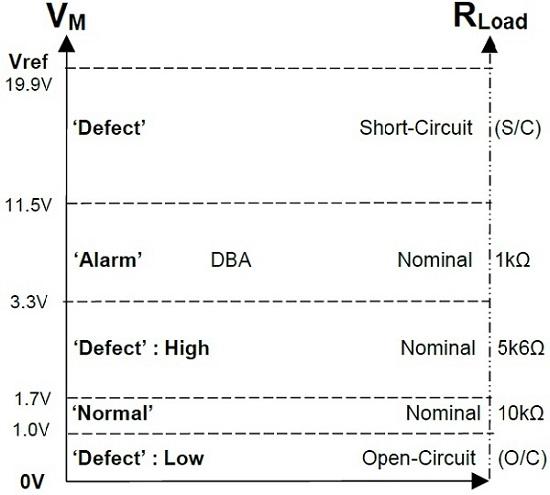
Datum levels NZS4512:2010 Detector Circuit
Figure below depicts the regions for the M-value voltages and the Zone Load (RL) values when the F4 panel is operating to NZS4512:2010.

Datum levels for NZS4512:1997 Detector Circuit
Figure below depicts the regions for the M-value voltages and the Zone Load (RL) values when the F4 panel is operating to NZS4512:1997.

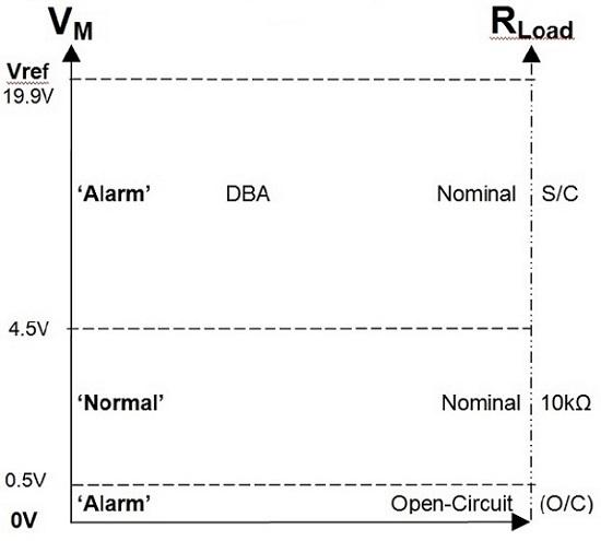
Datums levels for NZS4512:2010 DBA Circuit
Figure below depicts the regions for the M-value voltages and the Zone Load (RL) values when the F4 DBA Input is operating to NZS 4512:2010.
Datum levels for NZS4512:1997 DBA Circuit
Figure below depicts the regions for the M-value voltages and the Zone Load (RL) values when the F4 DBA Input is operating to NZS 4512:1997.
F4-RMAX
F4 Remote LED Mimic / Aux Relay Module
Compatibility
The F4-RMAX is compatible with F4 fire alarm panels fitted with version 5.02 or later firmware, and
version 5.05 or later F4 master boards.
The F4-RMAX board may be fitted in an F4 panel that also has an F4 Type 5 Sound Control Board,
provided the panel master board is version 5.05 or later.
Note: Pertronic Industries recommend that the RMAX board should be used with the standard
(flashing) mimic F100PDB12, in preference to the steady indication (F100PDB12S).
| Dip Switch Settings | |
|---|---|
| SW1 | Not Used |
| SW2 | Not Used |
| SW3 | Type 5 Global Z1 |
| SW4 | LED Mimic Enable |
If the panel is fitted with a F4 Type 5 Sound Control Board, then with RMAX connected
and SW3 OFF, zones 1, 2, 3 and 4 function as standard zones.