Masterboard Config Link Settings
| Function | Link |
|---|---|
| Defect Buzzer | MJ3 link fitted |
| NZS4512:2003 mode
|
LK1 link fitted |
| NZS4512:1997 mode | LK1 link cut |

System Fault Indication New
PCB HW >v5.05 S.W >v 5.02
| Source of Defect (LD1) | Position Code |
|---|---|
| Circuit 1 fault | Flash 1 is long |
| Circuit 2 fault | Flash 2 is long |
| Circuit 3 fault | Flash 3 is long |
| Circuit 4 fault | Flash 4 is long |
| Monitored Bell circuit fault | Flash 5 is long |
| Comms failure (monitors data communications to the Aux Relay Board) | Flash 6 is long |
| Battery Voltage Out of Range : below 12.2 Vdc or above 14.3 Vdc | Flash 7 is long |
| 20V Reference Out of Range : below 15.5 Vdc or above 26 Vdc | Flash 8 is long |
| Earth Leakage fault | Flash 9 is long |
| Internal Memory error | Flash 10 is long |
| Remote Mimic Aux Fault | Flash 11 is long |
| Remote Mimic Missing | Flash 12 is long |
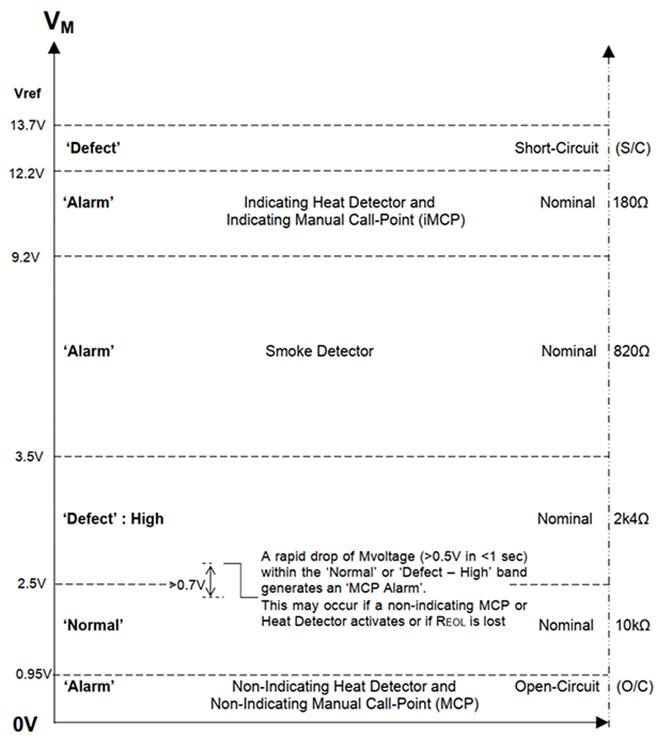
Datum Levels NZS4512:2010 Detector Circuit New
PCB HW >v5.05, S.W >v 5.02
Figure below depicts the regions for the M-value voltages and the Zone Load (RL) values when the F1 panel is operating to NZS4512:2010.
System Fault Indication Old
PCB HW >v1.5 S.W >v 3.04
| Source of Defect (LD1) | Flash |
|---|---|
| Detector Circuit fault | Flash 1 Long |
| Battery Voltage Out of Range: below 12.2Vdc or above 14.3Vdc. | Flash 2 Long |
| Earth Leakage fault | Flash 3 Long |
| Monitored Bell circuit fault | Flash 4 Long |
| Internal Memory error | Flash 5 Long |
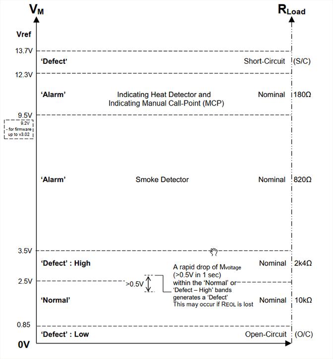
Datum Levels NZS4512:2010 Detector Circuit
PCB HW >v1.5 S.W >v 3.04
Figure below depicts the regions for the M-value voltages and the Zone Load (RL) values when the F1 panel is operating to NZS4512:2010.
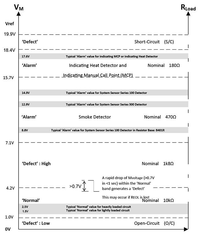
Datum Levels NZS4512:1997
PCB HW> v1.5, S.W >v2.4