Detector Circuits
All detector circuits are fully configured to accept smoke detectors, heat detectors or manual callpoints. A
mixture of detector or callpoint types may be used on any circuit.
All circuits must be terminated with a 10K, 1% end of line (EOL) resistor. An on board DC-DC converter
generates 20V for the detector circuits to enable a range of smoke detector types to be used on the F16.
When activated, heat detectors or manual callpoints (which open a detector circuit) operate the bells and
brigade signalling within 1 second. Smoke detectors or Pertronic indicating heat detectors give operation
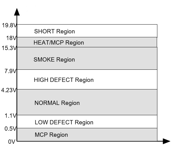
after a 6 second period. In operation, once a detector has triggered, the circuit is de-powered for 6 seconds to reset the detector. When the circuit is re-powered any further detector triggering within 90 seconds will cause the alarm to activate. This alarm verification facility (AVF) gives substantial protection against transient false alarm activation. To reduce false alarms a hard short circuit (less than 0.5V across the detector circuit) gives a defect signal.
Links are provided to disable the brigade signalling or system bells on a per circuit basis:
| Bell Link | Fire Link | Circuit Function |
|---|---|---|
| out | out | Normal operation – ring bells, call brigade (fire relay) |
| out | in | Bells Only operation |
| in | out | Apartment operation – smoke detectors ring bells only; indicating call points and indicating heat detectors ring bells and call brigade. Operating and restoring BCO will reset the smoke detectors.
Note: Use only indicating MCPs and indicating heat detectors for Apartment Operation |
| in | in | Indicator Only operation - (e.g. for sprinkler flow switch indicator purposes). In this case either a short or an open circuit gives non latching indicator operation. |
LED Fault Indicators
LED fault Indicators are provided for the following.
(a) Circuit defect indicators. These indicators latch although the defect signal itself is non latching.
(b) Battery Fault. When the F16 is in the 24 hour test mode, the Battery Fault LED is flashed momentarily every 2 secs to indicate low charger volts mode. This indicator latches if the battery voltage falls below 12.1 volts or exceeds 14.6 volts. The latched LED indicator flashes with a duty cycle of 1:1 if the battery voltage was low; and has a double flash if the battery voltage was high.
(c) Bell Fault. This indicator latches if the monitored bell circuits are either open or short circuit.
(d) System Fault. This indicator latches for the following:
Internal shift register fault.
Detector circuit power fault.
Door closure with off normal switches (after 45 minute time out).
External Defect input activated.
Extension board communications fault.
Mimic communications fault.
The indication operates by encoding the latched defect data into a pulse stream on the System Fault LED. If no latched defect conditions occur, then the LED is not activated. If one or more latched faults have occurred, a six bit pulse stream is displayed on the LED. If a particular fault is present it is represented by a long pulse, whereas if a fault is not present a short pulse is given. The position of a long pulse 1 to 6 in the 6-bit data stream corresponds to a particular fault type. The order of the long pulse in the encoded pulse stream is:
1st pulse long, shift register fault.
2nd pulse long, detector circuit power failure (20V).
3rd pulse long, door time-out fault.
4th pulse long, external defect.
5th pulse long, extender board communications error.
6th pulse long, mimic system communications error.
The pulse stream is repeated every 4 seconds.
(e) Extender Board System Fault.
This indicator latches for detector circuit power failure or for LED display shift register fault. The LED indicates an encoded 2-bit data stream (as in (d) above for the 6-bit data stream).
The encoded pulse stream is:
1st pulse long shift register fault.
2nd pulse long detector circuit power failure (20V).
The pulse stream is repeated every 2 secs.
Zone information LED's
| Flash Rate | Zone Status |
|---|---|
| on, non flashing | end-of-line failure or out-of-range on startup |
| quick (100ms on/off) | open circuit |
| normal (400ms on/off) | out of range |
| slow (1s on/off) | short circuit |
| short flash every 2s |
isolated |
Datum Levels