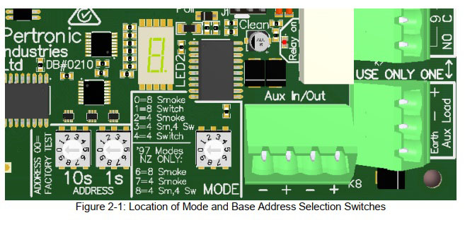
Configuration Options
The Mode switch is used to select the function of the inputs.
| Mode Rotary Switch Position | Function |
|---|---|
| 0 | All 8 Zones NZS4512:2010 |
| 1 | All 8 Zones configured as switch inputs |
| 2 | Zones 1-4, NZS4512:2010 and Zones 5-8 inactive ( i.e. a 4 cct responder) |
| 3 | Zones 1-4, NZS4512:2010 and Zones 5-8 configured as switch inputs |
| 4 | Zones 1-4 Configured as Switch Inputs and Zones 5-8 inactive
(i.e. a 4 input switch responder) |
| 5 | Spare.(equivalent to setting 0) |
| Mode Rotary Switch Position | Function |
|---|---|
| 6 | All 8 Zones NZS4512:1997 |
| 7 | Zones 1-4, NZS4512:1997 and Zones 5-8 inactive ( i.e. a 4 cct 1997 responder)
|
| 8 | Zones 1-4, NZS4512:1997 and Zones 5-8 configured as switch inputs
|
| 9 | Spare (equivalent to setting 0)
|
7 Segment Display
The on board 7-segment display is used to provide status information for off-normal events. The reporting is in the format of 2 consecutive characters: a number denoting the circuit and a letter showing the status.
| First char | Second char | Meaning |
|---|---|---|
| 1 .. 8 | A | Circuit in alarm |
| 1 .. 8 | d | Circuit in defect |
| 0 | P | 20V power |
| 9 | L | Power on the monitored 100v relay |
| 0 | I | Loop isolated |
| 9 | r | Relay monitor defect |
Defect Notification
Loop Responder Defects are displayed on the F100A and F120A Panels as shown in Table below.
| Condition | Defect Reported to Panel | F100A Display | F120A Display | |
|---|---|---|---|---|
| Conventional Detector Circuit Defects: | Circuit Short | Resistance between V+ and M terminals is < 60Ω | SHORT | SHORT CIRCUIT |
| Datum High Too many detectors (more than 40 detectors, but not enough to cause an alarm) | M Voltage in High Defect band | HI | High Defect | |
| Datum Low Open Circuit | Datum voltage Low Defect associated with the address of that circuit | LO | Low Defect | |
| Out-of-Tolerance EOL Termination (EOL < 8kW) | Use of EOL resistors outside the listed tolerance rating will be reported at power up or panel reset | HI | High Defect | |
| External Power Mode: Power Lost | PSU Defect reported through all 8 circuits of that board | PSU | Supply Defect | |
| Vref (20V) Circuit Voltage Failure | PSU Defect reported through all 8 circuits of that board | PSU | Supply Defect | |
| AA Loop Short | Isolator Defect reported through first circuit of that board | Device ISO and Loop Break | Device Isolator Defect and Loop Break | |
| EOL Resistor missing | Low Defect will be reported at power up or after 24hr test. | LO | Low Defect | |
| Circuit M point in defect band | Defect; associated with the address of that circuit. | DEF | DEFECT | |
| Switch Input Circuit Defects: | External Power Mode: Power Lost or too Low | Defect reported through all 8 circuits of that board | DEF | DEFECT |
| Vref (20V) Circuit Voltage Failure | Defect reported through all 8 circuits of that board | DEF | DEFECT | |
| AA Loop Short | Defect reported through first circuit of that board | Device DEF and Loop Break | Device DEFECT and Loop Break | |
Relay Output
One of two available relay outputs may be used, either a non-monitored set of clean contacts. The relay may be configured as any of the available types used in the F100A or F220A Panel (AUX, RLY, DHR, SND, etc).
The relay has one clean changeover contact (NC-C-NO), rated 2.0A @ 30Vdc - Form C. Or a monitored set of speaker contacts connecting to the 100V line input, rated 0.5A @ 125Vac.
The relay may be configured as any of the available types used in the F100A or F220A Panel (AUX, AUXM, RLY, RLYM, SND, SNDM etc
The monitoring can be enabled or disabled using link J1. Monitoring requires a 10k EOL Resistor. The monitored relay output may be spurred 2-way (2 x 22k EOL) or 3-way (3 x 33k EOL). The Relay (when monitored) will not activate if the EOL value is <5k.
When the relay is activated the associated red LED flashes at a rate of 1 second ON/OFF.
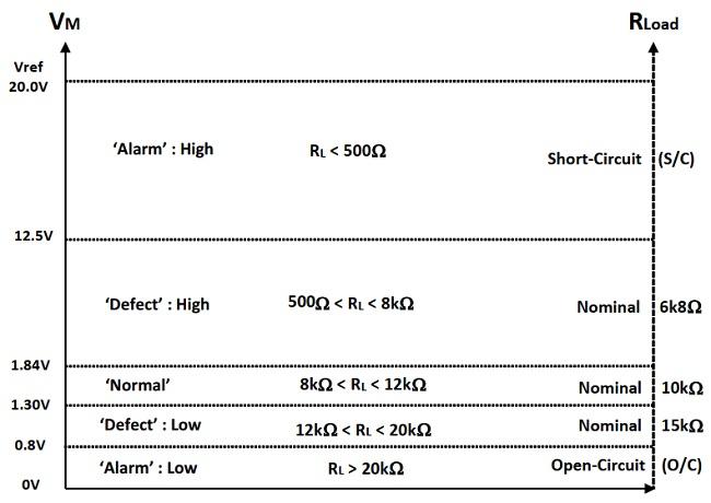
Conventional Detector’ 2010 Datum Level Graph
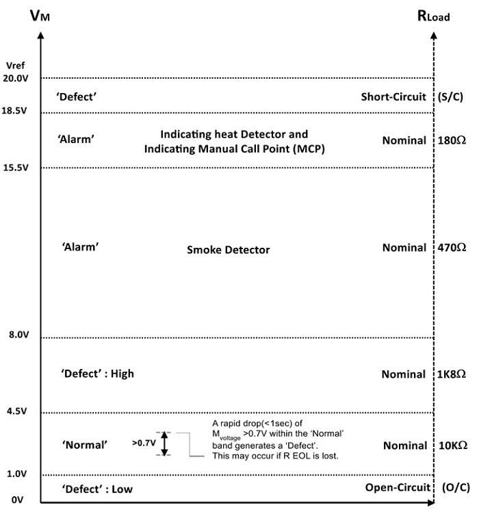
Conventional Detector’ 1997 Datum Level Graph
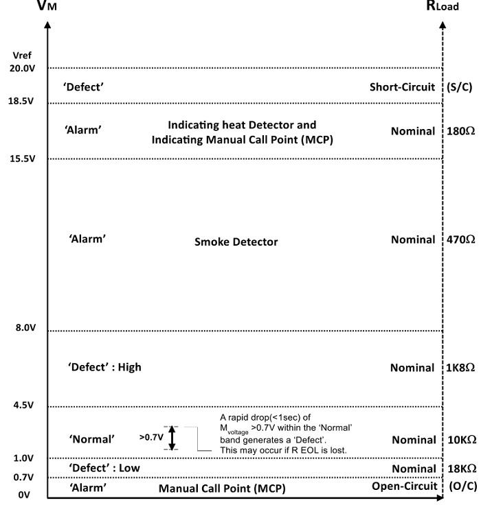
Switch’ Input Circuit
M-Point Voltage Indication depicts the regions for the M-valuevoltages and equivalent circuit resistance values.