Changing the Configuration
The link PROG ENABLE (located at the bottom right corner of the main PCB) must be inserted before a configuration can be changed. This enables the EEPROM memory, which holds the configuration data, to be updated. After changing or updating the configuration the link must be removed to prevent inadvertent alteration of the configuration.
Note: The PROG ENABLE link forms part of the door interlock system. If the link is still present when the door is closed, a door interlock fault occurs and the buzzer will sound.
Overview of the steps to change a Configuration
Insert the PROG ENABLE link.
Enable Programming Mode.
Select the System or the specific Circuit configuration to be changed.
Observe that zone circuit’s current configuration.
Select the option to be changed.
Make the change.
Exit Programming Mode.
Pull the PROG ENABLE link.
Detailed Configuration Steps
STEP 1: Insert the PRO ENABLE link
STEP 2:
Enable Programming Mode by holding down button F3 until the 2nd of two beeps is heard. The Programming Mode LED will illuminate.
 STEP 3:
Similar to the procedure described in Section 4.4, select the System or the specific zone circuit configuration that you wish to change by using F3 to cycle through them. Each time F3 is pressed, you will hear a beep. The LEDs indicate which is currently selected:
 If the System is selected the following LEDs are illuminated:
 The PROGRAMMING MODE indicator and the D1 SYSTEM indicator.
 Various configuration option LEDs (D3-D10, see Table 4-1)
If a zone circuit is selected the following LEDs are illuminated:
 The PROGRAMMING MODE indicator
 The D2 CIRCUIT indicator
 The appropriate zone circuit’s indicator, which is on the master board—illustrated at right—or in a similar display on an expander board, if included
 Various configuration option LEDs (D3-D10, see Table 4-1)
If any expander boards are used, pressing F3 will cycle through the additional circuits beyond 8 before looping back up to the System selection at the top. Stop pressing F3, of course, when you have reached the circuit which needs configuring.
STEP 4: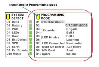 Observe the current configuration for the System/circuit whose settings need changing.
The existing configuration is displayed on indicator LEDs D3 through D10. These are located above the F1, F2, and F3 buttons on the master board and are illustrated at right.
Note:
The configuration displayed is only that of the system or specific circuit selected at the time.
The LEDs have different meanings and therefore labels when observing the System configuration versus the Circuit configurations. This is indicated by the two label columns to the right of the LEDs. The LED labels for the System configuration are in the first column with the SYSTEM heading while the Circuit configuration labels are in the second column with the CIRCUIT heading. LEDs display the existing configuration in this manner:
If an option is enabled, the corresponding LED will be ON.
If an option is not enabled, the corresponding LED will be OFF.
STEP 5:

Press F2 to select the option that needs to be changed. Each press of the button will produce a beep.
The first press of F2 selects the option represented by D3. The next press of F2 selects the option represented by D4, and so on through D10. (Only the selected option will have an illuminated LED: the other options’ LEDs will be OFF. Stop pressing F2, of course, after selecting an option that needs to be changed.
The first press of F2 selects the option represented by D3. The next press of F2 selects the option represented by D4, and so on through D10. (Only the selected option will have an illuminated LED: the other options’ LEDs will be OFF. Stop pressing F2, of course, after selecting an option that needs to be changed.
The current state of the selected option is displayed in this manner:
If the option is enabled, its LED flashes;
If the option is not enabled, its LED is steadily illuminated—not flashing.
After D10 is selected, the next time F2 is pressed, the indicator LEDs will again display the state of all configuration options for the currently
STEP 6:
 Press F1 to CHANGE the current option’s setting. As noted above, the state of the currently selected option is displayed in this manner:
 If the option is enabled, its LED flashes
 If the option is not enabled, its LED is on but not flashing
The configuration option is toggled with each press of F1
STEP 7:
More choices or, just finish and EXIT Programming Mode
- To navigate to another option that may need changing on the same circuit/System, press F2 to cycle through the options.
- To navigate to another zone circuit configuration or to the System configuration, press F3.
https://odoo-elearning.pertronic.net/f16e#table_of_content_heading_1653953396259_773 Note:If the PROG ENABLE link is removed BEFORE exiting Programming Mode, the configuration is not saved.
STEP 8:

Remove the PROG ENABLE link- but only AFTER exiting Programming Mode.
Displaying the Configuration
To enter Programming Mode in order to change the configuration, press and hold F3 until the buzzer beeps twice and the PROGRAMMING MODE LED (LED18) turns ON. This will take about 3 seconds. LED18 remains on while the system is in this mode.
There are two types of configuration; a ‘System’ configuration and a ‘Circuit’ configuration. Only one System configuration is required but a Circuit configuration is required for each individual zone.
In Programming mode, the SYSTEM LED (D1) indicates that the System configuration is selected and CIRCUIT LED (D2) that one of the Circuit configurations is selected. The individual zone circuit LEDs, Z1 to Z8, then further indicate which of those circuits is currently selected.

When Programming Mode is first entered the System configuration will be selected and displayed. D1 will be ON as well as some of the eight indicator LEDs (D3 to D10). These eight LEDs indicate the status of each of the System configuration options. The names of each of the System configuration options is marked on the circuit board in the SYSTEM column; aligned with the LEDs. If a configuration option is enabled, the corresponding LED is ON solid; otherwise, the LED is OFF. Firmly press and release F3 to select and display the first Circuit configuration. The indicating LED will move from SYSTEM mode (D1) to CIRCUIT mode (D2). The 8 indicating LEDs (D3-D10) will display the configuration for that zone circuit and the respective LED (marked Z1) will turn on next to the connector.
F3 can then be used to cycle through each of the individual zone circuits, including extender boards. The respective zone circuit LED will illuminate and the configuration will be displayed on LEDs D3-D10. When the last zone circuit is reached, the next press of F3 will loop back around and return to the ‘System’ configuration.
The configuration options for both System and Circuit configurations as well as Factory Default values are displayed in the table below:

Press and hold F3 until the buzzer beeps twice (about 2-3 seconds) to release the F16e from Programming mode.
System Assignments

Circuit Assignments

Circuit Defect
(LED3 to LED10). These indicators latch, although the ‘Defect’ signal itself is non-latching. The LEDs are located adjacent to each circuit input.
| Flash Rate | Circuit Status |
|---|---|
| ON - steady | End-of-line failure on start-up.
Latched alarm for indicator only circuit. |
| Quick (100ms ON/OFF) | Short-circuit |
| Medium (400ms ON/OFF) | High defect (out of range) |
| Slow (1sec ON/OFF) | Open-circuit (not if alarm in 1997 mode) |
| Short flash every 2s | Isolated |
System Defect
(LED16). This indicator latches and flashes when a system fault occurs. Any event in defect is identified by a 10-way LED Array (D1 to D10). These indicators latch ON (steady) when active.
| Defect Description | |
|---|---|
| D1 | Bells fault |
| D2 | Battery Fault |
| D3 | Memory or Shift Register hardware fault on Master PCB |
| D4 | LED Display hardware fault: EOL jumper missing, or incorrect number of LED boards |
| D5 | Door Time-Out fault: door closed for 45 minutes whilst door interlock fault exists |
| D6 | External fault |
| D7 | Sprinkler fault |
| D8 | Earth fault |
| D9 | Extender Board hardware fault, incorrect address or incorrect quantity |
| D10 | Mimic Communications error (RS485) |
Bell Defect
D1 latches if the monitored Bell circuits are either open or short-circuit. Refer to Table 5.3 below to decode the flash pattern.
| Fault | Flash pattern |
|---|---|
| No Bell fault, Bell circuit OK | LED OFF |
| Bell1 fault | Long - Short |
| Bell2 fault | Short - Long |
| Bell1 and Bell2 faults | Long - Long |
Battery Fault
D2 latches if there is a defect on either the battery or the power supply. Faults are defined as shown:
The power supply output falls below 25.66 volts or exceeds 28.6 volts.
The battery falls below 23.0V immediately, or below 24.0V for more than 55 seconds
While the fault exists, the panel continues to display ‘Defect.’
| Fault Condition | Flash Pattern | Panel Defect |
|---|---|---|
| Battery and Charger OK | LED OFF | No |
| Battery Missing or Defective | 1s ON/OFF | Yes |
| Battery Low, No Mains | 400ms ON/OFF | Yes |
| Mains Fail | Short flash, every 2 seconds | No |
| Power Supply Fault | Short flash, every 2 seconds | Yes |
Extender Board Defect
(LED9) This indicator flashes and latches in the event of a defect on the Extender board. If there is no fault, LED9 flashes briefly as the Extender board is polled from the Master board. If a fault exists, LED9 pulses a sequence of 5 flashes. The status of each condition monitored is indicated by the length of the flash: a long flash indicates a fault condition, and a short flash indicates the normal condition. The monitored events and the relevant flash code is shown in the Table below.
| Flash | Fault Description |
|---|---|
| 1st | Extender Supply Fault - less than 20V (nominal 27V) |
| 2nd | Communications Error |
| 3rd | Memory or Shift Register Fault |
| 4th | Configuration Memory Checksum Error |
| 5th | Flash/Program Memory Checksum Error |
| Constant ON | Not Polling. |
Datum Levels for NZS4512:2010 Circuits
Figure depicts the regions for the M-value voltages and the Zone Load (RL) values when the F16e panel is operating to NZS4512:2010.

Datum Levels for NZS4512:1997 Circuits
Figure depicts the regions for the M-value voltages and the Zone Load (RL) values when the F16e panel is operating to NZS4512:1997.

Cabinet Dimensions
| Description | Height mm | Width mm | Depth mm |
| Mini Panel | 410 | 450 | 130 |
| Large Panel | 600 | 450 | 130 |
| Tall Panel | 900 | 450 | 130 |